|
Physics 141 C Group 3 November 28, 2001 Aquilino S. Gamban Jr. Bein Felix Patrick Sanchez Lab Experiment 1 Who Are The 1ís and 0ís anyway? What happened :In our experiment, we were shown certain circuit diagrams. We were asked to make a real-life circuit out of it. As seen in the circuit diagram, we made use of the following materials: (Materials) 555 IC Ė an integrated circuit whose purpose is further discussed later. The definition of an Integrated Circuit (IC) is that it is a tiny electronic circuit (an assemblage of electronic elements) used to perform a specific electronic function, such as amplification; it is usually combined with other components to form a more complex system.
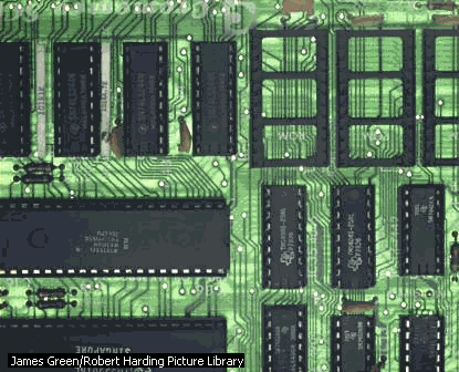
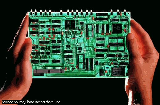
Integrated circuits (ICs) make the microcomputer possible; without them, individual circuits and their components would take up far too much space for a compact computer design. Also called a chip, the typical IC consists of elements such as resistors, capacitors, and transistors packed on a single piece of silicon. In smaller, more densely-packed ICs, circuit elements may be only a few atoms in size, which makes it possible to create sophisticated computers the size of notebooks. A typical computer circuit board features many integrated circuits connected together Capacitor Ė also called an electrical condenser, it is a device for storing an electrical charge. In its simplest form a capacitor consists of two metal plates separated by a nonconducting layer called the dielectric. Circuit board (for practice) Ė a non-conductive board on which electric components are mounted and electrically connected by thin strips of metal. It has strategically placed linking holes with metal connections underneath for easy circuit making.
Insulated copper wires Ė conducting devices covered with a nonconductive material. Insulation is essential to prevent accidental/unintended wire connections that might cause errors in an experimental setup (breakage of materials, wrong outputs, short circuits, the burning of faura building, etc.) LEDís Ė A Light-Emitting Diode (LED) is a device that emits visible light or infrared radiation when an electric current passes through it. Potentiometer Ė a device that controls the flow of current within the circuit by the turning of a knob. It is also known as a variable resistor. Resistors Ė a component of an electric circuit that resists the flow of direct or alternating electric current. Resistors can limit or divide the current, reduce the voltage, protect an electric circuit, or provide large amounts of heat or light.
After the materials have been prepared, we did the experiment in a step-by-step process so that everyone can follow with minimum confusion. We were to do these steps:
(Procedure/Observation) After doing the steps, we were asked to answer the following questions: (Questions)
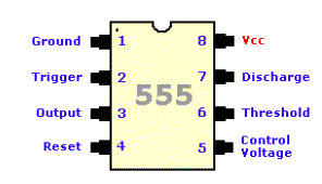
With the help of our observations during our experiment and some research, we were able to devise the following answers: (Answers) 1. The purpose of the resistors in Steps 1 and 2 is to control (in this case, to limit) the current passing through the LED to 10 mA or less, which is the safe level for the LED to operate (it will only light up if the current passing through it is within this range). Since we know that LEDs operate with 1.2 volts, by Ohmís Law (V = IR), we determine that to have a current that is 10 mA or less, the resistance should be at least 380 Ω. Therefore a 470 Ω resistor is sufficient to ensure that the current passing through an LED is within the safe operating level. V = IR, where 5 V = V + 1.2 V (5 Ė 1.2) = (10 * 10-3)(R) R = (3.8)/( 10 * 10-3) 2. To recognize the 1ís and 0ís using the circuit we built in Step 3, we connected the probe to both the ground and +5, one at a time. When the probe is connected to the ground, the LED nearer to the +5 turned on, indicating that it is the logic "0" or the "low". In the same manner, the LED nearer to the ground was turned on when the logic probe was connected to the +5, indicating that it is the logic "1" or "high". Note: logic "1" represents the range from 2.5 to 5.0 volts while the logic "0" is within 0.0 to 0.8 volts. 3.The capacitor and the resistor are important parts of the circuit to be able to control the speed of the change from "1" and "0". The amount of resistance from the resistors will determine how much current will pass through to the capacitor to charge it. The capacitor then acts as storage for this current. The 555 IC will then act as an oscillator, switching form high to low, depending on the voltage from the capacitor. So, the amount of current passing through the circuit and how fast the capacitor charges and discharges will determine the speed of the change from "1" and "0" and these factors are controlled by the resistors and the capacitor. This explains why a potentiometer connected to the resistors will allow us to control the speed of blinking of the LEDís of "1" and "0". 4.As mentioned earlier, the 555 IC will act as an oscillator. The 555 will switch from "1" and "0" as shown by the blinking of the LEDís. The 555 can do this with the help of a capacitor connected to pin 2 (trigger) and to pin 6 (threshold). As the capacitor charges and discharges, these two pins check how much voltage passes through. When the voltage reaches 1/3 of the voltage in the circuit, pin 2 will tell pin 3 to go high and the capacitor begins to charge. When the voltage reaches 2/3 of the voltage in the circuit, pin 6 will tell pin 3 to go low and the capacitor starts to discharge. Since the probe is connected to pin 3, when pin 3 goes high, the LED for high lights up and when it goes low, the LED for low lights up. This cycle goes on and on with the capacitor alternately charging and discharging.
Along with the answers, we were also able to comment on what happened to our experiment: (Comments) - the Circuit Board made life easier for us since it makes circuit making less confusing. Furthermore, most of the materials needed (especially the ICís) easily snuck into the holes the board provided (except for those totally deformed resistorsÖargh!). - wires caused more confusion than help since it made our circuit look cluttered. It resulted to a greater chance for human error to occur, thatís why we had to double check the given circuit diagram to make sure our connections were correct. Theoretically, however, the circuit had some changes. It is because of the internal resistance of the wire provided. The circuit had some additional resistance. - the 555 IC, upon our research, is actually a timer. Wow. - LEDís are very fascinating that it amused us to add more of them in our experiment. We havenít figured out however (at that time) on how to make many diodes blink at a certain rhythm or pattern. Upon understanding what the 555 IC does though, we concluded that using this I just wouldnít work (efficiently) for our goals. - the capacitor works as a delay instrument for the circuit. Charges are contained within a capacitor until a certain amount of voltage "fills" it up and "spills" it hole. However, as the current decreases, we were able to observe that it takes a longer time for the capacitor to charge and discharge, thus making the blinking of lights slower than the usual. It is seen when we added the potentiometer in the circuit and varying the amount of resistance that passes through the circuit. - during this experiment, we were also able to appreciate the "educational value" of having to troubleshoot our circuit. Through careful analysis and simple trial and error, we were able to point out the different causes of malfunction in our circuit. Having to take apart and rebuil our circuit several times provided us with a very "enriching" experience on how to properly go about in solving technical problems in electronics.
We were also able to analyze the properties of a 555 circuit and these were our hunches (heheheÖ)
(555 IC) An IC, or an Integrated Circuit is a ready-made, tiny electronic circuit used to perform a specific electronic function, such as amplification. ICs are usually combined with other components to form a more complex system. It is formed as a single unit by diffusing impurities into single-crystal silicon, which then serves as a semiconductor material, or by etching the silicon by means of electron beams. As defined an IC is a circuit that performs a simple task, and when combined with other circuits, can provide a more complex task or use. The simple task of a 555 IC is very basic but very important. This IC has the ability to sense the amount of voltage present in the circuit allowing it to give a certain output depending on that voltageís amount. With that ability the 555 IC can be used as a timer. The IC synchronizes the circuit on when a certain activity should occur, making certain tasks happen at this given period, and another at this period , and so on and so forth. The circuit made with the 555 then is more regulated, organized, and best of all, more predictable. As seen in our experiment, the 555 made our LEDís blink alternatively in a uniform manner, opening a connection to the zero logic at one period of time (which obviously means closing the other), and the 1 logic at another period of time. The experiment shows the consistency of the 555 circuit with the help of the potentiometer, wherein the blinking of the LEDís were still uniformly done at a certain rate.
Eureka! The 555 IC is a Timer!
Inside a 555 Timer IC |


