|
Group C/4 A2 Rene Russell Santos Mikhail Regalado Jeremiah Chua back to Group C/4 Entry Page Laboratory Report # 1 I. Circuit Diagrams: Step 1
Step 2
Step 3
Step 4 ( blinking lights using the 555 circuit)
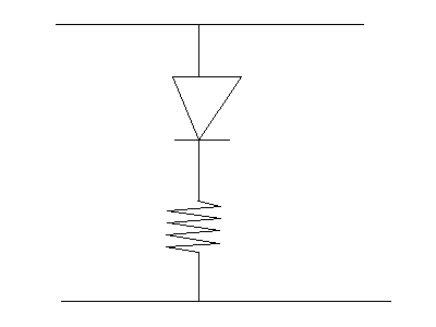
II. Evaluation and Analysis of Circuit In step 1 and step 2, the resistors serve to lower the current in the circuit so that the current would be in the acceptable range, with respect to the Light Emitting Diodes (LEDís). The LEDís have a certain tolerance level for the current. A high current in any type of circuit would lead to an increase in temperature of the circuit. The higher the current, the higher the temperature goes. The LED, When the current in the circuit is greater than the tolerance level of the LED, the LED would burn out. In our lab experiment the LED has a maximum tolerance of about 0.01 A. It also has a voltage drop of 1.2 Volts across it. That leaves about 3.8 volts for the resistor we are going to connect ni the circuit. We need a current that is less than or equal to 0.01 A, and across the resistor, we have voltage drop of 3.8 volts. To find the proper value for the resistor we can use Ohmís Law. The Ohmís law states that the voltage drop across any element is equal to the current passing through that element multiplied by its resistance ( V = IR ). Therefore, to get the proper resistance value, we divide the Voltage drop by the current. We will get 3.8V / 0.01 A, or 380 Ohms. Therefore we can use any resistor greater than or equal to 380 Ohms. In the experiment, we used 470 ohms. In step 3, we can recognize, or rather differentiate, the 1ís from the 0ís by connecting the probe to either the positive or the negative (ground) voltage source. The circuit in step three is designed such that if the probe is connected to the negative terminal (ground) electricity would flow through the upper LED (in the diagram) since its other side is already connected to the positive terminal (+5 volts). We can consider this as logic 1. On the other hand, if the probe is connected to the positive terminal, electricity would flow through the lower LED since the other end is already connected to the negative terminal. We can consider this as logic zero. The 555 circuit has 8 pins. Of all the eight pins, we only used 6. Pins 4 and 8 were connected to the positive terminal, 1 was connected to the ground, 3 was connected to the probe of the circuit in step 3, and pins 2 and 6 were connected, and their connection was connected to a capacitor connected to the ground. Pins 2 and 6 actually measures the amount of charge in the capacitor. If the amount of charge is 1/3 its maximum, the whole circuit recognizes this as a logic zero. When the amount of charge is 2/3 its maximum, the whole circuit recognizes this as logic 1. And so, with the charging and discharging cycle of the capacitor, the 555 chip is used to "oscillate" between logic one and logic zero, and the lights seem to blink. The speed of the oscillation would depend upon the resistors. Since capacitors store charges, the higher the current, the faster the capacitor charges, and then, when it is full, it discharges. Since the resistors can actually lower the current, they can change the rate at which the capacitor stores charges. This enables us to be able to control the speed of oscillation by varying the total resistance in the circuit, therefore increasing or decreasing the current as we want it to be. |


