|
1
|
go to top
next
previous
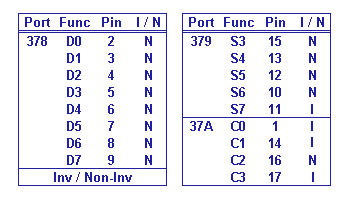
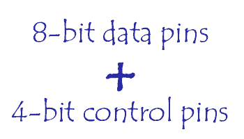
The port has three groups of pins, namely, the data group (D0 to D7), the control group (C0 to C3), and the status group (S3 to S7). C4 to C7 and S0 to S2 are reserved by pins and are not available to the user. All control pins are outputs, in the same way that all status pins are inputs. Some pins are Non-inverting, others are Inverting.
The "base port address" is 0x378. This number is found in memory at address 0040:0008 (Segment 0040 & Offset 0008).
|
Pin Designations of Printer Port

|
|
|
2
|
go to top
next
previous
A C-language command of "outportb(0x378, data);" or "outportb(0x37A, control);" will cause the port to present bits at the data and control pins, respectively.
It is theoretically possible, therefore, for the PC to control any number of devices connected to it through appropriate decoding circuits. However, there is speed limitation. The more circuits there are to control, the slower would be the polling time. In practice, fast applications are normally performed via the motherboard slots.
This application will need to be performed with full address decoding.
This can be a very tricky process. In order to overcome some of the limitations here, one could, first, take an old discarded printer or I/O card and strip it of all the IC's and other devices on it. Next, attach the PCB with the appropriate decoding and latch circuit to the old I/O board and solder the addresses, data, handshaking, and other circuit elements to the appropriate copper on the old I/O board. In this way, one could avoid damage caused by electrical imperfections in the production of the "plug-in" board.
|

|
|
|
3
|
go to top
next
previous

|
Reading data into the computer is achieved by presenting active logic data at the status pins and reading it with a C-language (or equivalent) command of "inportb(0x379);".
Due to the 5-bit limitation of the status port, one normally takes in the "higher nibble" (a S3 to S6) first and AND it with binary "0111 1000" shifts it once to the left to become Input_HI. Then present the lower nibble, AND it with binary "0111 1000" and shift it to the right three times to become Input_LO. Finally perform an OR operation on Input_HI and Input_LO to become the full 8-bit input, Input_FULL_VALUE.
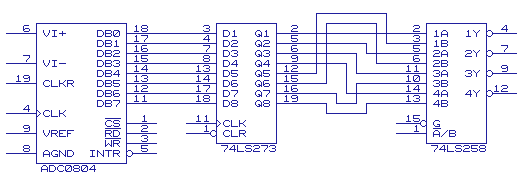
When using 74LS258, care must be taken to compensate for its inverted output.
The circuit above depicts an ADC0804 with its output latched to a 74LS273. 8 bits of data are sent to the 74LS258, from the 74LS273 wired in such a way that the lower nibble goes to the "A" inputs and the higher nibble goes to "B" inputs. "A" is chosen by bringing pin #1 to logic "1" and "B", to logic "0". This function is normally performed through one of the control pins of the printer port.
|
|
|
4
|
go to top
next
previous

|
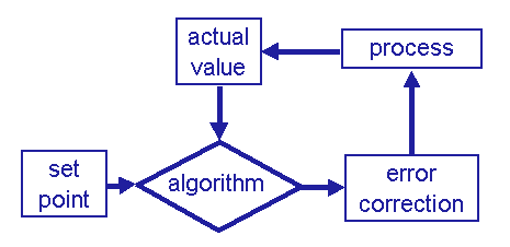
In a control application, one would normally specify a "set point". The evaluation algorithm performs a check to see if the process parameter has the same value as the set point. If it is higher or lower, the algorithm will send the appropriate corrective signal to the process to bring the parameter value to (or back to) the set point.
Some applications provide algorithms to send a pre-calculated error correction value that will bring the process parameter at the value of the set point, without overshooting or undershooting it by too much.
Take the electrical power system as an example, and assume that it is operating with a system load of 5,000 megawatts, at a frequency of 60 Hz. An algorithm could be developed in such a way that a 0.05 Hz drop in system frequency could be corrected with the addition of "X" megawatts of generation to correct the frequency to exactly 60 Hz, within "Y" amount of seconds.
Other control procedures go by the name "PID control" (for Proportional, Integrative, and Derivative), or "Feed-forward", a procedure similar to the one described above.
|
|