|
1
|
go to top
next
previous
Addresses used for the control of COM 1

|
"Write" and "Read" data port. Write the data to address 0x3f8 to send data out through the serial port to another computer connected to COM 1. If a modem is connected to it, this data will be sent through the telephone line connection of the modem. When data comes in, it will also be read from this port.
Use a C-language program or "Function AH=00 of BIOS Interrupt 14H" to initialize the serial port (baud rate, parity, stop bits, and number of bits per character).
Force the "Request to Send" and "Data Terminal Ready" to their active mode before a read/write operation can be implemented. This is performed by sending 0x03 to port 0x3fc.
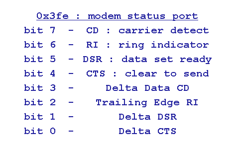
0x3fd and 0x3fe are used to monitor the status of the serial port to have the assurance that data sent have been sent, and data received is valid.
|
|
|
2
|
go to top
next
previous
Cable Wiring Connections

|
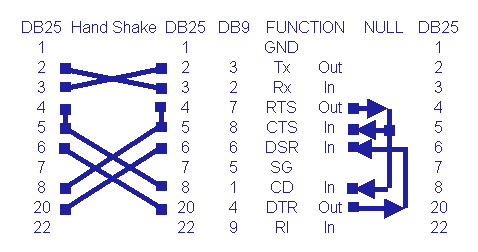
The diagram above depicts the connections for the 25-pin (DB 25) connector and the corresponding equivalent 9-pin (DB 9) connector. The left part of the diagram is a computer-to-computer communication with strict handshaking provisions.
The portion on the right side of the diagram tricks the computer to believe that the other computer has responded with a "clear to send" (CTS) when it sends a "request-to-send" signal (RTS). At the same time, it also makes the computer believe that it has detected a carrier ("carrier detect" - CD) signal. At the same time, when the computer says that it is ready ("data terminal ready" - DTR), it gets a signal to say that the other computer is also ready ("data set ready" - DSR).
The connectors of both computers are provided with the same jumpers, to trick their circuits into believing that there is a valid handshake. This trickery has to be done to go around the hardware limitations that prevent data from being passed back and forth if the corresponding handshaking signals are not present.
|
|
|
3
|
go to top
next
previous

|
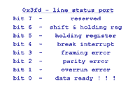
Read 0x3f8 if bit 1 is set (logic "1"). After the read operation, bit 1 will be reset (logic "0").
Transmit data by sending it to 0x3f8 when bit 1 is reset, AND bits 6 and 5 are both set.
The more convenient way is to use the BIOS. It automatically performs these checking functions for the programmer.
|
|
|
4
|
go to top
next
previous

|
|
0x3fe is used when writing programs that manage data communication via the telephone line.
|
|


