|
1
|
go to top
next
previous
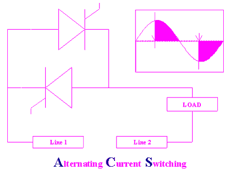
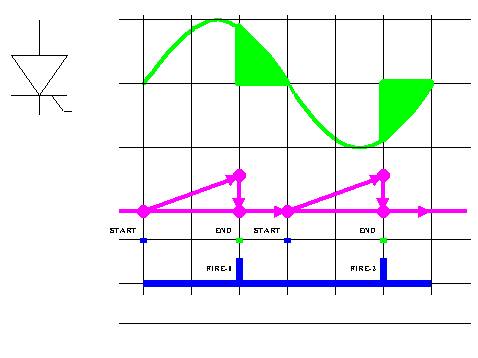
The solid-state switch is "closed" at an "angle" determined by a timing circuit. The energy, which is proportional to the area bounded by the voltage curve is sent to the load to do work.
The circuit on the right delivers chopped alternating current to the load. One would normally introduce a filter to prevent the development of harmonics that could cause the overheating of whatever iron (in the form of iron core) that is used in the load equipment.
|
|
|
|
2
|
go to top
next
previous
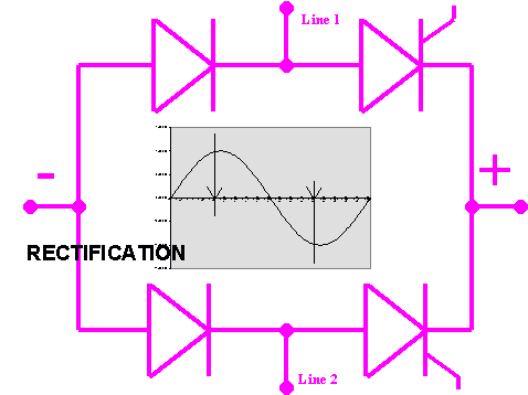
The circuit at the right acts in the same way as the preceeding one. Alternating current is fed to the terminals indicated as Line1 and Line2. Direct current is made available at the "+" and "-" terminals.
The configuration is such that the circuit delivers direct current to the load. This could be a DC motor, a power supply, a battery charger, or any other device that calls for a DC supply.
|
|
|
|
3
|
go to top
next
previous
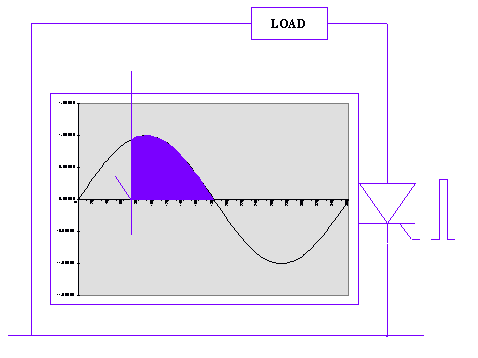
This chart is a representation of the thyristor that fires at the positive part of a sinusoidal wave. Energy delivered is maximum when the thyristor fires at the beginning of the positive or negative cycle.
Strictly speaking it can fire only after the voltage reaches approximately 1.2 volts. The circuit should be designed such that it can draw current at this voltage equivalent to or higher than the "latching current" of the chosen thyristor.
|
|
|
|
4
|
go to top
next
previous
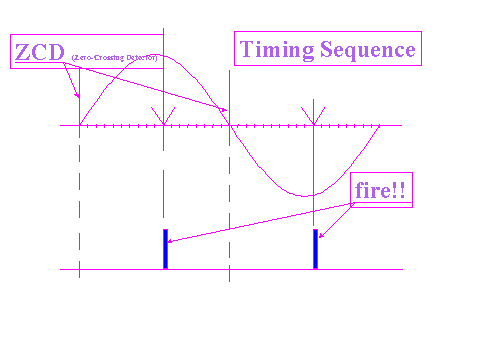
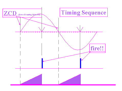
The firing circuit is designed to recorgnize the exact time that the voltage crosses the "zero axis". This is called a "zero-crossing detector" (ZCD).
The circuit will then measure the time that has elapsed after zero-crossing. After a specific time has elapsed, the circuit will send a trigger firing signal to the "gate" of the thyristor, forcing it to start conduction (turn on). Since "time" is proportional to the angle traversed by the vector, this is sometimes exchangingly referred to as the firing angle.
|
|
|
|
5
|
go to top
next
previous
The diagram at the right consolidates what has been said about the various functions of the firing circuit.
|
|
|
|
6
|
go to top
next
previous
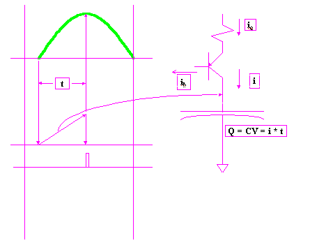
A timing ramp is generated by charging a capacitor from a "constant-current source" until the terminal voltage of the capacitor hits a certain pre-set level.
A higher charging current would charge the capacitor faster. The ramp produced will appear to the oscilloscope as having a steeper slope than when a smaller charging current is fed to the capacitor.
|
|
|
|
7
|
go to top
next
previous
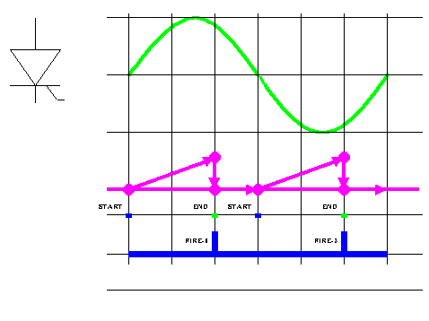
The objective of the designer of the firing circuit is to provide a trigger to the gate of the thyristor within the "0 to 180" degree range, and within the "180 to 360" degree range.
Another objective is to be able to vary the firing angle from a remote control device. For this reason, the circuit should be capable of being interfaced with a such a remote control device. A PC computer is used in the CE 150 course.
|
|
|
|
8
|
go to top
next
previous
The computer will generate binary codes that will be translated into analog signals to control the output of the constant-current source for a higher or lower charging current.
The current industry trend is for the computer to generate binary codes that correspond to so-called "control set points".
|
|
|
|
9
|
go to top
next
previous
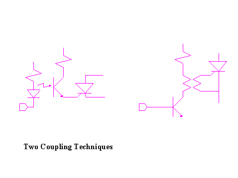
Most thyristor applications are live, or commonly called "hot". For this reason, there is the necessity for the computer to be electrically isolated from the thyristors.
The diagrams at the right shows two examples of common industry coupling methods. These are the "optical" and the "magnetic" coupling methods.
|
|
|

